|
||
| ; | ||

| ; | ; | ; | ; | ||||
|
|
; | Tune-up Procedures
The Following Tune-up Steps
|
 |
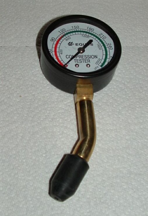 |
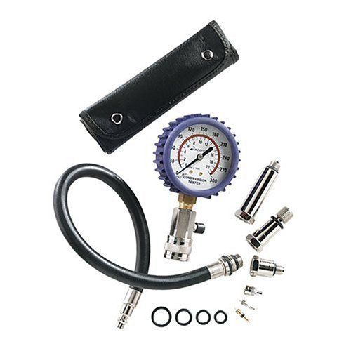
Screw-In Tester |
Press-In Tester |
Compression Testers
Note: A handy trick is to wrap thin strands of copper wire around both ends of the spark plug wires--one loop for Cylinder #1, two loops for Cylinder #2, and so on. This way there is no question about which wire goes where. Refer to the diagram at the beginning of the Valve Adjustment procedure to see which cylinder is which and where the firing point for each is on the distributor.
Note: To prevent damage to the spark plug wires, be sure to disconnect the wires by first twisting then pulling on the wire's boot, not on the wire itself.
Note: I find that a 3-inch extension between the ratchet and spark plug socket is needed for cylinders #1 and #3.
Note regarding spark plug removal -
Someone wrote - My Bug's spark plugs are very tight. When trying to loosen them, they squeak and creak. I have not applied to much force for fear of stripping the head's threads. Rob responded - I don't have any simple answers on this one - the best you can do is wait for a really cold night and remove the plug in the morning so the engine is as cold as it can be. Steel expands and contracts more than aluminium, so the plug is likely to contract more than the head, making it easier to remove. It's quite possible ithe plug has been cross-threaded when it was installed. If so, the thread will almost certainly be damaged when you remove it. This is one reason why I always start the plug into the head with my fingers. If you can turn it in a turn or so just holding the threaded top then it will never cross thread.
Note: If you are using the press-in type of tester, you will need an assistant to turn the engine over. With the screw-in type, you can screw the tester into each spark plug holder successively and turn the engine over yourself.
Caution: If you're using the screw-in tester, do not use the long-reach adapter on short-reach holes (1/2" long spark plug threads). If the long-reach adapter is used in short-reach holes, it may hit the top of the piston and damage the engine.
Note: The test results should be over 100 pounds and within about five pounds of each other. Low readings indicate need for an engine overhaul.
Diagnosis
- On a normal cylinder, compression should increase quickly and uniformly during each compression stroke of the engine until a top (or peak) reading is reached.
- If compression is low on the first stroke, builds up on the following strokes, but does not reach normal value, the piston rings may be worn or leaking.
- If compression is low on the first stroke and does not increase on following strokes, leaking valves may be at fault.
- If the compression value is higher than the manufacturer's specifications, carbon build-up may be present in the cylinder or on the piston.
- If compression readings on two adjacent cylinders are 20 pounds (or more) lower than the other cylinders, the cylinder head bolts may be loose (cylinder heads leaking).
- Recheck cylinders with low compression readings by injecting approximately 10cc of engine oil into each cylinder (through the spark plug hole (and retesting). If the compression reading increases a little, the problem is probably worn, broken, or poorly seated piston rings. If the compression reading remains the same, leaking or damaged valves may be at fault.
- Before re-installation of the spark plugs, proceed to Step #2 below, "Inspect, Adjust and Install Spark Plugs."
Note: The point of this test is to seal the rings momentarily to increase the compression. The oil helps seal worn rings a little, but it does NOT help burned/tight valves or leaking heads - so this simple test can sometimes tell you where the problem lies. What actually happens is that the rings wear on the outside where they scrape the cylinder, so they get thinner, creating a larger gap at the back of the ring-groove in the cylinder, plus the gap in the rings grows wider. The oil won't do much with the actual gap in the rings, but it helps fill in the extra space behind the rings in the ring grooves, and seals the contact between the rings and the groove itself -- the bottom of the groove and bottom of the ring particularly as the piston moves up for the compression test.
Step 2. Inspect, Adjust and Install Spark Plugs.
Note: See Rob's excellent article on Reading Spark Plugs, which includes a link to some excellent spark plug pictures). Also, credit must be given to John Connolly at Aircooled.Net, who gave us a lot of very helpful hints that you will find in the following.
Note: Always remove the spark plugs with the engine cold. When hot the hole swells inwards and the plug swells outwards, resulting in a tight plug thread and the risk of galling the threads. Bob Hoover has strong feelings about this -- (Removing the plugs with the engine cold) "is the standard rule for aluminum heads, and has been since the 1920's. The world is filled with engines having aluminum heads, but about the only folks who seem to have trouble with stripped spark plug holes are kids with Volkswagens. I wonder why that is..."
Things you will need:
- Two 13/16-inch spark plug sockets - one with a rubber insert to hold the plug, and one without.
- A ratchet (3/8-inch drive).
- A 3-inch extension, 3/8-inch drive.
- A universal, 3/8-inch drive.
- A 6-inch length of rubber breather hose, 1/2-inch ID.
- Pull the spark plug connectors off all four spark plugs (if you have not done so already for the compression test.
- Inspect the wires and the rubber seals on the ends. If they are worn, torn, or otherwise defective, replace them.
- Stow the wires so you'll know what goes where (see the note above under Compression Test).
- Using the 3/8-inch ratchet, the spark plug socket with the rubber insert, and the 3-inch extension (if necessary), loosen all four plugs until they're hand tight using the spark plug socket on a 3/8" drive ratchet (and appropriate extension if needed). Use the extension and socket to screw out the last few threads by hand.
- Lay the spark plugs out in a pattern to match the way they came out of the engine.
- If you are going to reuse the plugs, inspect them carefully, comparing them to the Reading Spark Plug pictures. Put the plugs back into the cylinder they came from. If necessary, clean the plugs or install new ones.
- Set the gap between the bottom bent electrode and the center straight electrode to 0.028" using the feeler gauge on the gapping tool. The bent electrode can be carefully bent in and out with the gapping tool to make the adjustment.
- Before installing the new plugs, make sure to remove the screw cap from the top of the spark plug, and make sure that there is a gasket on each plug.
- Slip the 6" rubber breather hose onto the WIRE end of the plug.
- Using the hose as a "socket" extension, hand-thread the plug into its hole. Do your best to flex the hose as necessary so the plug aligns properly with the plug threads.
- Once you are confident that the plug is started well in the hole (you can feel it), pull the hose off, put on the ratchet and socket WITHOUT the rubber insert (and the 3-inch extension and universal as necessary). Torque the plugs to 22 ft-lb with the engine no more than warm. Never over tighten the plugs -- a snug-and-a-tug should do it.
- Put the plug wires on the same way you took them off. Make sure the rubber seals are pushed down firmly on the spark plugs and that the seal is seated properly in the hole in the tin.
Note: The large rubber seals around the spark plug leads are important -- they seal the spark plug holes in the tin and assure that cooling air is directed to the heads rather than going into the engine compartment. The seals MUST be replaced if they won't stay snuggly against the hole in the tinware.
Note: If you have difficulty getting the socket onto the spark plug, it's usually because the tin doesn't line up with the plug, or there is something (e.g., the intake manifold on dual-port engines) in the way. A small mirror may be helpful to see interferences around the spark plug.
Note: The spark plug gap increases as the plugs wear. John Connolly at Aircooled.Net likes to start with a new plug gap of 0.025". After 10,000 miles that gap of 0.025" will be closer to 0.040". It is better to run the plugs toward optimum then away from it.
Note: Bob Hoover advises - Be darn sure to use a dab of anti-sieze on the threads of the plugs and make sure that the compression washer is in place. Install the plugs BY HAND until the thread is full depth. Don't put a wrench on the plugs until they are fully threaded into their bores. And if you can't thread them in by hand, you've got galled threads and need to do something about it -- it ain't gonna heal itself.
Rob's advice is just the opposite. He says - Never use "never-seize" or other compounds on the spark plug threads. The higher head temperatures in VW engines (20-40C higher than water cooled engines) can cause these to "cook," resulting conductivity problems. So long as you remove and install plugs when the engine is cold you won't have a problem with seizing, and you'll also avoid stripping plug threads. Hot heads make the threads very tight on the plugs, so let the engine cool before removing them.
It's up to you.
Note: The rubber hose is used here so you won't drop the plug somewhere you don't want it (like inside the tin. Ideally the hose will grip the plug, but you will still be able to turn the plug.
Note: The plugs should start in the holes and turn fairly easily by hand. But please note - The cylinder heads are soft aluminum, so be careful you don't cross thread the plugs when screwing them in. Always start the thread by hand for a turn or two so you can tell if it's cross threaded before any damage occurs (there's just enough room to hold the threaded top of the plug in the hole in the tinware). This is one reason why it is wise to use a rubber hose on the plug - if the plug does cross thread, the hose will slip and it won't hurt anything.
Note: You do not use the socket with the rubber insert to tighten the spark plug, as the spark plug may be quite tight in the socket, and removing the socket from the spark plug difficult. Some people apply some silicone grease onto the plug before putting it in the socket; this will make removal of the socket much easier. Just be sure to wipe the grease off the end of the plug before installing the spark plug wire.
Step 3. Distributor (Cap, Rotor, Points, Condenser)
Note: Ignition adjusting must be done on a cold engine. You will start with the engine cold, and end with it warm.
- Quoting John Muir -- Open the rear boot. Get out the stool and sit down. Contemplate the air-cooled beauty before you.
- Inspect the distributor/carburetor connections (if any).
- Pry the two spring clips off the distributor cap with the screwdriver. Inspect the cap for cracks and excessive pitting on the contacts. If defective, replace it. If okay, store it out of the way.
- Pull off the rotor and inspect it. If the contacts are excessively pitted or worn, replace it.
- If the rotor is okay, store it away in a safe place.
- With the rotor off, take a look in the center of the spindle it rides on. If your distributor has a felt pad in there, put a few drops of oil on it (engine oil is fine) to lubricate the distributor drive. Don't overdo it though -- a few drops only. Some distributors don't have this felt pad - in that case skip this step.
- To see how the points work, first make sure the transmission is in neutral. Then put the 19mm socket on the alternator nut and rotate the engine clockwise, the way it runs. Watch the points open and close as you turn the engine. The points are adjusted to 0.016" (50o on the dwell meter) at the point where they are separated the widest.
- Inspect the points and the nylon rider on the moveable point. If they are excessively pitted or the nylon rider is badly worn, replace them. Always replace the condenser at the same time you replace the points.
- If the points are okay, check the gap. The points are adjusted to .016 inches (0.4 mm).
- If necessary, adjust the point gap by loosening the hold-down screw and moving the stationary point by prying the slot in the point mechanism with a screwdriver. (The hold-down screw must be loose enough to allow movement of the point but tight enough to hold the point in place when you change its position.)
- Check the point setting with the dwell-tachometer as follows:
- Brighten up the sparking end of the rotor (if you're not replacing it) using emery paper (a file will remove too much material). Put the rotor back on the shaft.
- Brighten up the four contacts inside the distributor cap if they look a little burned.
- Replace the distributor cap, checking the spark plug and coil wires to make sure none of them have come loose.
- Connect the green clip from the dwell-tachometer to Terminal #1 on the ignition coil (the one to which the green wire from the distributor is attached -- it's on the left). Connect the black clip to ground (one of the bolts that holds the coil to the fan housing is a good place. Make sure the dwell-tachometer wires don't become tangled with the fan belt!).
- Start the engine and allow it to warm up. Turn the Function Selector on the dwell-tachometer to DWELL; observe the reading on the Dwell Scale. (If your dwell-tachometer doesn't have a 4-cylinder scale, note the reading on the 8-cylinder scale and multiply it x 2).
- The correct reading is 50o +/- 2o (25o +/- 1o on the 8 cylinder scale). If too high, the point gap is too narrow. If too low, the point gap is too wide.
- Readjust the point gap as necessary.
- How to Keep Your Volkswagen Alive -- Step-By-Step Procedures for the Compleat Idiot.
Note: If the distributor on your car is a double-vacuum advance type, there should be two vacuum hoses from it to the carburetor. The advance vacuum hose comes from the left side of the carburetor right below the stepped cam. It connects to the rear (rear of the car) port on the silver vacuum chamber on the side of the distributor. The retard vacuum hose comes from the rear port on the carburetor, just to the right of the throttle lever. It connects to the port on the front and bottom of the vacuum chamber on the distributor. It is essential that these vacuum hoses be hooked up correctly; the car will run VERY poorly (if at all) if they are reversed.
If you have a single-vacuum dual-advance distributor (SVDA - the best match for the 34PICT/3 carburetor), there will be only one vacuum hose connected to the port on the left side of the carburetor. The vacuum hose as well as the ports on the rear of the carburetor and on the intake manifold MUST be plugged to prevent air from being sucked into the carburetor when timing the distributor.
Dave noted that it made no difference in the timing whether the vacuum line was attached or unattached and plugged. Rob helped him understand the situation better -
The vacuum line should not be working at idle, so the "remove and plug" routine is just insurance. If the idle set too high, though, it certainly CAN be noticed. The vacuum part should work almost instantly if you blip the throttle at idle (giving maybe 8-10 degrees more than the idle setting) and the centrifugal part should start to work (as you slowly increase the throttle) at about 1200 rpm, and should be all (about 32 degrees) in by about 2500 rpm. The vacuum is still additional to that so the throttle cruising at 45-50 mph (2500-2600 rpm) should result in about 40 degrees of advance.
BUT - Given all of that, Dave later discovered that the left-hand port on the carburetor was providing no vacuum at all. Dave tried to remove a clog with a thin wire but to no avail. He ended up replacing this Pierburg with a rebuilt, rebushed carburetor from (Keith Doncaster - keifernet@hotmail.com). Keith rebushes and refurbishes carburetors for a very reasonable cost.
Note: Find the small notch on the rim of the distributor body. It should be either at about 5 o'clock for vacuum distributors (e.g., SVDA) or 7 o'clock for centrifugal-advance distributors (e.g. 009). When the rotor is at this position, the #1 spark plug fires. The rotor turns clockwise; the firing order is 1-4-3-2. It is a good idea to mark the ends of the spark plug wires in some way so you know which is which.
Note: If you have an Ohm Meter, touch one lead to the center of the rotor and the other to the tip. Resistance should not exceed 10,000 ohms.
Another Note: A reader provided the following interesting tip: When you need to clean up the end of a rotor arm, drag it over a tire. Sounds odd, but there's just enough abrasion to clean it up perfectly, with no risk of damage due to over enthusiasm .
;
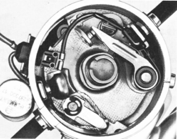
Breaker Points in the Distributor
Note: That's one school of thought. Another one says, "If it ain't broke, don't fix it!" In other words, if the condenser is working, leave it alone. Your choice.
Note: If the points are only slightly burned/pitted, they can be touched up in the car using a small flat "points file", which is about the size of a fingernail file. The points themselves are very hard material, and will wear the file surface blunt, so the tip of the file can be broken off with pliers once it has been used, then next time you are using a new part of the file surface. If the points need filing, adjust the gap afterwards.
;
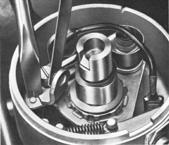
Points Being Adjusted
Note: The adjustment device consists of (1) a notch in the end of the point assembly and (2) a little bump on the distributor plate. You adjust the point gap by prying the notch against the bump with a screwdriver.
;
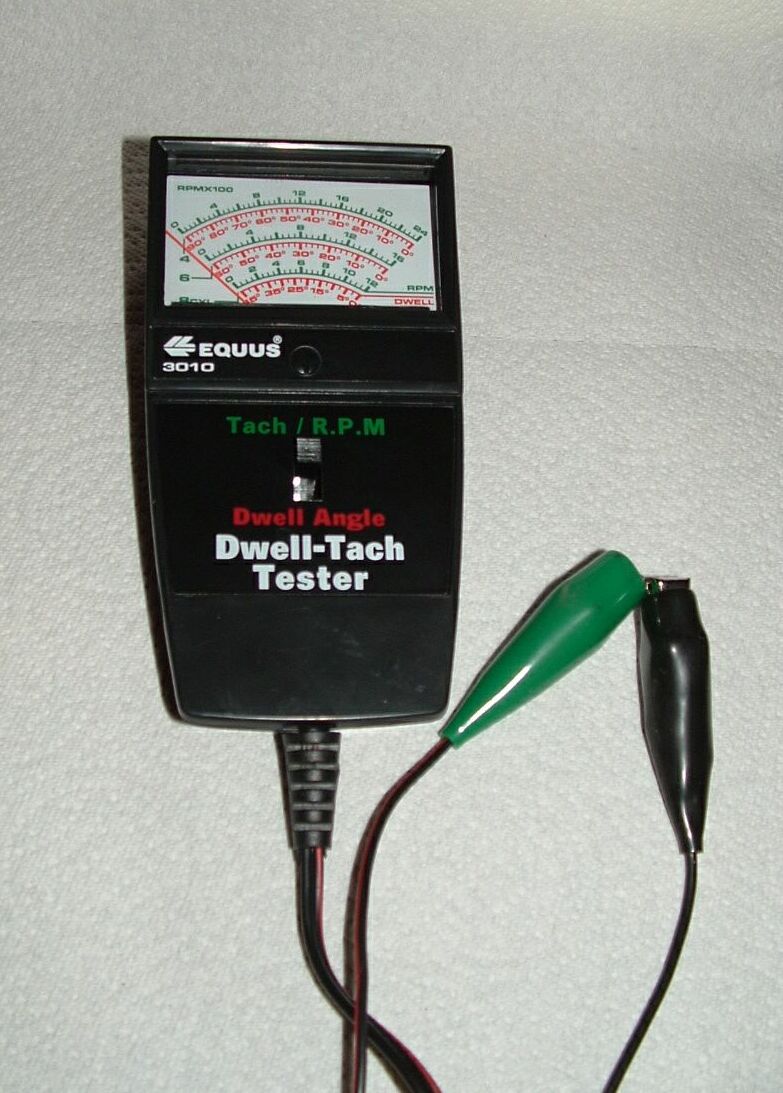
Dwell-Tachometer
Note: Changing the point gap changes the timing. If you change the gap, be sure to check the timing per Step 6 below.
Step 4. Check the Condenser.
- Remove distributor cap.
- Turn crankshaft until the points are fully open (any cylinder).
- Disconnect the green wire from the distributor to the coil.
- Connect a test lamp wire to the ignition coil terminal and the other lead to the distributor wire.
- Switch on the ignition but do not start the car. If the lamp lights, the condenser is grounded internally and must be replaced.
- Reconnect the green distributor wire to the coil.
- Pull the main high tension wire from the coil, and with the ignition on, turn the engine over. The spark should jump a 1/4 inch gap to ground. If it won't jump this distance, replace the condensor.
Step 5. Adjust the Idle.
Note: When troubleshooting the engine, eliminate all other possible trouble sources before you touch the carburetor adjustments. Adjusting the idle rpm should be the last step in a tune-up. Otherwise, valve and ignition adjustments will upset the previously-made idle adjustment.
Note: The idle and timing are interrelated and must be set at the same time. See the Timing Procedure below.
Note: The idle adjustment must be made when the engine is warm, the points are properly adjusted, and the engine is timed.
- Set the parking brake firmly and block the wheels. Put the transmission in neutral.
- Set the switch on the dwell-tachmeter to RPM (see the picture of the dwell-tachometer above).
- Connect the green clip to the negative (-) terminal on the coil (the one to which the green wire from the distributor is attached).
- Connect the black clip to ground (again, the bolt that attaches the coil to the fan shroud is a good place).
- If you have a single-vacuum dual advance (SVDA) distributor, remove the vacuum hose from the distributor and plug it to prevent air from being sucked into the carburetor. Also remove and plug the vacuum hose to the aircleaner to prevent air from being sucked into the intake manifold. (Regarding removal of the vacuum hose, see the following note.
- Start the engine and run it for at least five minutes to warm up.
- Allow the engine to idle. Remove the aircleaner and make sure that the automatic choke is fully open (it's the butterfly valve in the top of the carburetor -- with the engine warm the valve should be standing straight up) and the stepped throttle (fast idle) cam on the left side of the carburetor is all the way up so that the screw on the top of the throttle arm is resting on the lowest point on the cam.
- Note the rpm on the tachometer; you will adjust it to 850 - 900 rpm (the specification given in the book) as follows:
- Adjust the screw on the top of throttle lever so that it just touches the fast idle cam. Then turn it in 1/4 turn.
- Turn off the engine momentarily.
- Slowly turn in the Volume Control screw until it bottoms lightly. Then back it out 2-1/2 to 3 turns. This is the starting point for this screw.
- Restart the engine and adjust the Bypass Screw until you obtain the desired idle speed (850 - 900 rpm) as indicated on the dwell-tachometer. Turning the bypass screw out increases the rpm; turning it in decreases the rpm.
- Turn the Volume Control screw one way or the other to obtain the highest idle speed, then turn the screw clockwise (in) until the engine speed drops by about 25 rpm.
- Reset the idle to 850 - 900 rpm using the Bypass Screw.
Note: If you have a Capacitive Discharge Ignition (CDI) system installed on your car, hopefully you provided a test lead to which the dwell-tachometer can be attached. See the CDI wiring diagram.
Note: If you have a single vacuum distributor, when you adjust the timing later you will remove the vacuum line from the vacuum canister on the distributor and plug it to prevent air from entering the carburetor. When you set the idle speed, it shouldn't make any difference whether the vacuum line is removed or not, since at the lower idle speed the airflow through the main throat is very small. But if the idle speed is up a little the vacuum line WILL see a vacuum signal, and this will affect the advance. So the safe bet is to remove and plug the vacuum line and set the idle speed with it off - that way you are sure that you are only dealing with the centrifugal advance. The vacuum advance does not begin to work until about 1200 rpm (so it shouldn't affect the idle speed at all of course).
Note: The idle is set with a "Volume Control" screw and a "Bypass" screw of the left side of the carburetor. The Volume Control screw is the lower one and is the smaller of the two. Both are recessed into the carburetor and must be accessed from the side with a screwdriver. The Bypass screw (the larger one) is used to adjust the idle speed. The Volume screw is the idle mixture setting.
Note: This step is very important. It opens the throttle butterfly in the carburetor 0.004" so that the idle jet will work properly.
Also Note: In the exploded view of the carburetor, this screw is called the "Idle Control screw." This is misleading, as this screw is NOT used to set the idle as it was on earlier carburetors. The Volume Control and Bypass screws on the left side of the carburetor are used to set the idle speed.
Note: The Bentley Manual says, "Do not adjust the mixture by turning the Volume Control screw unless (1)you have installed a different carburetor, (2) you have removed, repaired, or rebuilt the carburetor, or (3) the engine is producting excessive emissions." This adjustment is critical - use a flashlight and make sure you have a good line of sight. The Volume Control screw out of whack can cause exasperating performance problems.
Note: This step is a little tough--it's hard to see a 25 rpm difference on the tachometer, especially if you're using a tachometer designed for an 8-cylinder car. Do the best you can.
Note: If you have trouble setting the idle speed with the timing correctly set (see the next step), go to the section below regarding the Idle/Timing Interrelationship.
Step 6. Set the Timing.
Please see also our Timing Discussion.
IMPORTANT NOTE: It is important to understand the four-stroke design of the aircooled Volkswagen engine (intake, compression, combustion and exhaust), both when adjusting the valves and setting the ignition timing. As you turn the crankshaft through its complete four-stroke cycle you will note that you turn the alternator pulley around TWICE. You will encounter TDC at Cylinder #1 and again at Cylinder #3. To time the spart properly, you MUST make sure that it is Cylinder #1 at TDC and not Cylinder #3 (voice of experience!). If you are at all unsure, run our Finding Top Dead Center procedure below.
Note: This procedure gives the timing specifications for both the vacuum-advance (single and dual) and centrifugal-advance (009) distributors, as all three are used with the 34PICT/3 carburetor. The timing is correct (at idle) when the spark leaves the distributor exactly when the correct timing mark on the crankshaft pulley lines up with the crack in the crankcase.
- Preliminary Settings -
- First make sure the valves, the point gap and the idle are properly set. Changes in point gap and idle speed change the timing.
- Find Top Dead Center (TDC) -
- If you are uncertain as to which mark is which on the crankshaft pulley, you must find the point at which piston #1 is at Top Dead Center on its compression stroke. A quick and dirty method is the pencil/straw test; a better and more definitive way is to check the position of the #1 valves. First, the pencil/straw test.
- Find TDC with the pencil/straw test.
- Remove the #1 spark plug.
- Remove the distributor cap and find the small notch on the rim of the distributor body that marks the position of the #1 spark plug wire (5 o'clock for SVDA distributors; 7 o'clock for 009 distributors).
- With a 19mm socket or 19mm box-end wrench (ring spanner) on the alternator nut, rotate the engine (clockwise -- the way it goes) until the rotor is approaching the #1 spark plug position (the notch you found in the rim of the distributor). This will place the piston near the top of its stroke.
- Insert a pencil (eraser end first) or straw into the #1 spark plug hole until it rests on the top of the piston.
- With the 19mm wrench (spanner) on the alternator nut, and while holding the pencil/straw on the top of the piston, move the crankshaft back and forth across the #1 spark plug position until you find the point at which the piston is highest in the cylinder (i.e., the pencil/straw is at its furthest point out of the spark plug hole). This is Top Dead Center. There will be a few degrees of crank movement where the pencil/straw is not moving - you want the middle of this crank movement.
Note: The #1 cylinder is on the right side, closest to the front of the car.
Note: This is a very thin little notch in the metal - it's easiest to find if you run your fingernail around the rim of the distributor body.
Note: Make sure that the pencil/straw is horizontal, not lying at an angle across the cylinder. If you're not careful, you make break off the end of the pencil, which will then fall down into the cylinder! Not good!
Note: It is important to get the piston roughly at TDC (TDC mark near the split in the crankcase -- Step c. above). Then place the pencil/straw in the hole and rock the piston back and forth to find the center of the no-movement position. If you put the pencil/straw in with the piston at or near BOTTOM of its stroke, and place it so that it is sitting at an angle across the cylinder (the spark plug hole is on the upper side of the head), then rotate the crankshaft, the piston may push the pencil sideways break off the end. Removal of this end bit of the pencil is expensive! That's why the straw is suggested as an alternative - it is stiff enough for the test but bendy enough not to break off inside the cylinder.
- Find TDC by checking the position of the #1 valves.
- To do this you must remove the rocker cover on the right-hand side to expose the valves.
- First rotate the crankshaft so that the timing marks are at the top of the pulley.
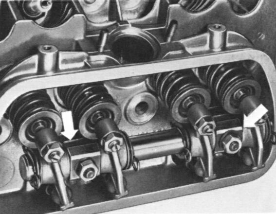
- By looking at the valve springs, note the position of the valves on the #1 cylinder (the outer valves are the exhaust valves and inner ones are the inlet valves).
- So if either/both of the valves for the #1 cylinder are open (the springs are compressed), the piston is on the exhaust stroke, so you will need to turn the engine one complete revolution so the timing marks are again at the top and both #1 valves are shut (the springs/tappets are loose).
- Replace the rocker cover.
- The distributor rotor should now be pointing at the notch on the distributor rim. The stock VW disributors put the rotor arm at the 5 o'clock position for #1, but some aftermarket distributors have #1 at a different position. This does not matter, so long as you then install the spark plug wires on the distributor with #1 at the position the rotor arm is pointing to, then install the remaining wires in 1-4-3-2 order, clockwise around the distributor.
- On the crankshaft pulley, with piston #1 exactly at TDC, make a mark (with white paint) exactly opposite the split in the crankcase if the pulley does not already have a TDC mark (some do, some don't). This will be your TDC mark and the starting point for other timing marks you will make. You will find the timing mark(s) that apply to your configuration by carefully measuring from the TDC point around the rim of the crankshaft pulley. For example, 30 degrees advance is 46.5mm to the right of TDC. This is particularly useful if you are using a 009 distributor, which must be timed to maximum advance, rather than set static or at idle.
- While you're at it, rotate the pulley 180 degrees and paint a different mark on the pulley there. You can then use this point when you adjust the valves (this is the point at which pistons in cylinders #2 and #4 are at TDC).
Note: Dave finds it easiest to raise the rear of the car and place it securely on jack stands, then remove the right-rear wheel. Rob says - "Putting it on jack stands would make the job a tad easier I guess, but I just lie on the ground under the right side of the engine and pop the rocker cover off you can get at the valves easy enough to wriggle them with the car still on it's wheels.
Rocker Arm Assembly
Note: Since on the firing stroke both valves must be shut, two loose springs/tappets for #1 with the timing marks at the top means it's on the firing stroke. One full turn puts that cylinder at the end of the exhaust stroke, and since the exhaust valve stays to open a few degrees AFTER TDC and the inlet valve opens a few degrees BEFORE TDC, one or both valves will be tight/compressed when the piston is at the top of the exhaust stroke, so it's easy to tell the difference.
- Make Your Timing Marks -
- The distances around the pulley (arc distances) for the various
timing marks are calculated using the following formula -
arc distance = 2(pi)(r)(alpha)/360
where -
pi = 3.1416
r = the radius of the pulley (in mm)
alpha = degrees of the appropriate arc
(e.g., the appropriate timing advance). - Timing the Various Distributors -
- Vacuum-advance only distributors: From 1961 to 1971, Type 1 distributors were vacuum-advance only -- they had no centrifugal advance. These distributors are timed at 7.5o BTDC; this point is found by measuring on the rim of the crankshaft pulley 11.5 mm to the right of the TDC notch.
- Dual-advance distributors: From the TDC mark, measure on the rim of the pulley 7.6 mm to the left from the TDC notch and mark with white paint; this is 5o ATDC, the point at which the dual vacuum advance distributor is timed.
- 009 and SVDA distributors: Measure on the rim of the crankcase pulley 11.5 mm to the right of the TDC notch. This is 7.5o BTDC; mark this point with white paint. This is the point at which the centrifugal advance (009) and single-vacuum dual-advance (SVDA) distributors are preliminarily timed (the maximum advance at 3500 rpm will be the final timing point for these distributors).
- Maximum advance: From the TDC mark, measure on the rim of the crankcase pulley 46 mm (for a 175 mm diameter pulley) to the right of the TDC notch. This is 30o BTDC; mark this point also with white paint. This is the maximum advance point at 3500 rpm, the timing point for 009 and SVDA distributors.
The arc distances that follow are based on a pulley diameter of 175mm, thus a radius of 87.5mm. Be sure to measure the diameter of your pulley and use the radius of your pulley in the following calculations.
Note: The double-vacuum advance distributor must be timed with the engine idling, using a strobe timing light. The 009 and single-vacuum distributors CAN be statically timed at 7.5o BTDC, but timing with a strobe light is recommended. If an electronic ignition system like Compu-Fire or Pertronix has been installed, the distributor MUST be timed with a strobe light.
- Timing With Stroboscopic Timing Light -
- Setting the 009 Centrifugal Advance, Single-Vacuum Dual Advance (SVDA) and Vacuum-Only Distributors with a Strobe -
- Set the parking brake firmly and block the wheels. Put the transmission in neutral.
- Make sure that the maximum advance timing mark (as determined above) is clearly visible on the crankshaft pulley (i.e., marked with white paint).
- Attach the inductive pick-up clip on the timing light around the #1 spark plug wire, close to the spark plug and away from the other spark plug wires to avoid interference. Observe the arrow on the clip pointing to the spark plug (if there is such an arrow).
- Power to the strobe light is provided through the red clip. Attach it to a convenient power source. We use the terminal on the right side of the coil (the one with the wires to the automatic choke, backup lights and idle solenoid -- terminal #15). Alternately (and perhaps more conveniently), you can use the positive terminal on the alternator.
- Attach the black clip to ground (the bolt on the fuel pump and the rear carburetor nut are convenient places, but make sure the wire doesn't become tangled with the fan belt!).
- Attach the dwell-tachometer in accordance with the idle procedure above.
- Start the engine. Adjust the idle to 900 rpm using the procedure above.
- Turn off the engine and loosen the distributor clamp bolt (10mm) enough so the distributor requires a strong twist to be moved but will stay where it is moved to.
- Stow the timing light, then restart the car. Point the timing light at the split in the crankcase and pull the trigger on the timing light. When the trigger on the strobe light is pulled, with the engine running, the strobe produces a very bright light which flashes every time the #1 spark plug fires. This bright light is used to observe the relationship between the timing mark on the crankshaft pulley and the split in the crankcase.
- With the engine idling at 900 rpm, adjust the preliminary timing to the 7.5o BTDC mark by turning the distributor one way or the other.
- Pull the throttle lever down to increase the engine rpm while you hold the strobe light on the crack in the crankcase, and watch the marks on the crankshaft pulley in the strobe light. The TDC mark and idle marks should appear to move to the left (advance) as the rpm's increase to about 3500 rpm, and the maximum advance timing mark should come into view.
- Turn the distributor one way or the other to set the maximum
advance (at about 3500 rpm) to the 30o BTDC mark
you made earlier.
Note: Stated another way -- with the engine running at a high rate of speed (about 3500 rpm), turn the distributor one way or the other to set the spark advance such that the 30o BTDC mark appears in the strobe light at the split in the crankcase.
- Return the engine speed to normal idle.
- Shut off the engine, and while holding the distributor in the correct position, tighten the 10mm distributor clamp bolt. (See the note above regarding the nut on the forward end of the clamp bolt.) Restart the engine and recheck the maximum advance timing.
- Allow the engine to idle and, with all of the vacuum hoses still disconnected and plugged, reset the idle speed to spec (850-900 rpm) per the idle procedure above.
- Check the idle timing and make a mark on the crankcase that
that point. In the future you can set the idle timing at this
point (vacuum hose removed from the SVDA distributor and plugged).
- Reattach the vacuum hose on the SVDA distributor, and, if applicable, to the vacuum port on the intake manifold.
- Setting the Dual-Vacuum Distributor with a Strobe
- Make sure that the appropriate timing mark (see above) is clearly visible on the crankshaft pulley (i.e., marked with white paint).
- Attach the inductive pick-up clip on the timing light around the #1 spark plug wire, close to the spark plug and away from the other spark plug wires to avoid interference. Observe the arrow on the clip pointing to the spark plug (if there is such an arrow).
- Power to the strobe light is provided through the red clip. Attach it to the terminal on the right side of the coil (the one with the wires to the automatic choke and idle solenoid -- terminal #15).
- Attach the black clip to ground (the bolt on the fuel pump and the rear carburetor nut are a convenient places, but make sure the wire doesn't become tangled with the fan belt!).
- Attach the dwell-tachometer in accordance with the idle procedure above.
- Start the engine and allow it to idle at about 900 rpm (if the idle speed is other than this, adjust the idle in accordance with the idle adjustment procedure above).
- Point the timing light at the split in the crankcase and pull the trigger on the timing light. When the trigger on the strobe light is pulled, with the engine running, the strobe produces a very bright light which flashes every time the #1 spark plug fires. This bright light is used to observe the relationship between the timing mark on the crankshaft pulley and the split in the crankcase.
- Turn off the engine and loosen the distributor clamp bolt (10mm) enough so the distributor requires a strong twist to be moved but will stay where it is moved to.
- Restart the car and aim the timing light at the crankcase pulley at the point where it passes the split in the crankcase. Move the distributor one way or the other until the proper timing mark on the pulley (as seen in the strobe light) lines up with the crack in the crankcase.
- Shut off the engine, and while holding the distributor in the correct position, tighten the distributor clamp bolt. (See the note above regarding the nut on the forward end of the clamp bolt.) Restart the engine and recheck the maximum advance timing.
Note: Timing with a stroboscopic timing light must be done with the engine warm. If your timing is so out of whack that the engine will not start, the SVDA and 009 distributors can be timed statically to get you in the ballpark. See the Static Timing procedure below.
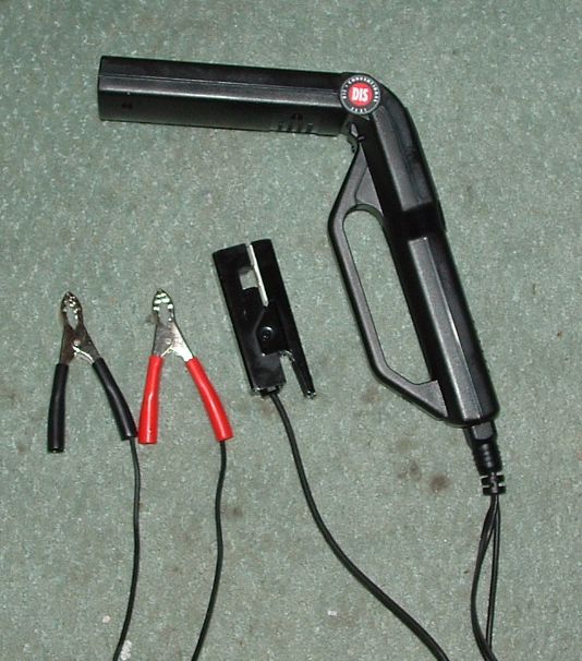
Stroboscopic Timing Light
The strobe light emits a very bright light which is flashed from a pistol-like instrument when the #1 spark plug fires. Be sure to read the instructions that come with the strobe light.
Note: The approximate idle timing setting for the centrifugal advance distributor (009), the single-vacuum distributor, and the vacuum-advance only distributor, is 7.5o Before Top Dead Center (BTDC). This means that as you view the 7.5o mark at the crankcase split (with the strobe), the TDC mark on the pulley will be about 11.5mm to the LEFT of the crankcase split when the distributor is properly timed. Again, this is the APPROXIMATE timing setting at idle.
Important Note regarding vacuum lines:When timing the vacuum-only distributor, the vacuum line(s) must be attached. The vacuum line on the single-vacuum dual advance (SVDA) distributors must be removed from the vacuum canister on the distributor and plugged to prevent air from being sucked into the carburetor during timing. For BOTH the centrifugal-advance (009) and SVDA distributors -- if there is a vacuum hose running from a port in the intake manifold under the carburetor up to the air cleaner, this hose must be removed and plugged as well, for the same reason. Be sure to plug it such that air will not be sucked into the intake manifold.
Summary regarding vacuum hoses during timing: Just make sure the vacuum ports on both the carburetor and the intake manifold are PLUGGED so air won't be sucked in during timing.
For these distributors, the advance timing is more important than the idle timing. Ideally it should be 28-30o advanced at 3500 rpm, then should return to something close to 7.5o BTDC at idle (900 rpm). The centrifugal-advance portions of these distributors vary -- if the maximum advance is set to the correct 28-30o BTDC at 3500 rpm, an idle timing in the range of 5-8o BTDC should result.
Note: If your car is equipped with a Capacitive Discharge Ignition system, power to the coil is provided indirectly through the CDI unit. In this case, just attach the red clip on the strobe light to any convenient 12-volt power source. As indicated above, we use the wire to the automatic choke, only because it's convenient.
Warning! If you do attach your timing light to the automatic choke connection, be VERY CAREFUL that the black wire from the ignition switch (terminal #15 on the coil) does not accidentally come disconnected from the choke connection and drop to touch the alternator body when the ignition is on. If this happens, you will get a shower of sparks, and worse -- you will burn out your ignition switch! (Voice of Experience -- this has happened to me TWICE! You'd think I would learn... I'm getting good at replacing ignition switches!)
(See our Ignition Switch Replacement procedure.)
Note: It's a good idea to secure the timing light up and away from the fan belt after hooking it up and while starting the car, to keep the wires from getting tangled up in the fan belt. Tucking it in front of (front is front, remember) the stock air cleaner, or anywhere else in the engine compartment where it is up and away from the fan belt, is a good idea.

Distributor Clamp
Note: You may find that the nut on the forward end of the clamp bolt turns when you try to loosen or tighten the clamp bolt. It is difficult to get a wrench on this 10mm nut; we finally kept it from turning by wedging a small flat-blade screwdriver against it.
Note: Turning the distributor clockwise retards the spark; turning it counterclockwise advances the spark.
Note: These distributors are timed with both vacuum hoses ATTACHED. If you're not sure which hose goes where, see our article on Dual Vacuum Hoses.
Note: If your car is equipped with a Capacitive Discharge Ignition system, power to the coil is provided indirectly through the CDI unit. In this case, just attach the red clip on the strobe light to any convenient 12-volt power source. We use the wire to the automatic choke (though some timing lights, when connected in this manner, will prevent the engine from starting -- for a reason we have yet to determine).
Warning! If you do attach your timing light to the automatic choke connection, be VERY CAREFUL that the wire(s) from the ignition switch do not accidentally become disconnected from the choke connection and drop to touch the alternator body. If this happens, you will get a shower of sparks, and worse -- you will burn out your ignition switch! (Voice of Experience -- this has happened to me TWICE! You'd think I would learn... I'm getting good at replacing ignition switches!)
(See our Ignition Switch Replacement procedure.)
Note: When timing the double-vacuum advance distributor (two vacuum hoses), the throttle valve in the carburetor must close adequately for accurate timing adjustment. To check, disconnect the vacuum retard hose (attached to the front of the vacuum chamber and rear of the carburetor) with the engine idling. The timing mark should move 15-18mm to the left. If not, the carburetor needs to be adjusted.
Note: You may find that the nut on the forward end of the clamp bolt turns when you try to loosen or tighten the clamp bolt. It is difficult to get a wrench on this 10mm nut; we finally kept it from turning by wedging a small flat-blade screwdriver against it.
Note: The correct timing setting for the dual-vacuum distributor is 5o After Top Dead Center (ATDC). This means that as you view the 5o mark at the crankcase split (with the strobe), the TDC mark on the pulley will be about 7.6mm to the RIGHT of the crankcase split.
Note: When you change the timing, the idle speed will also change. The reverse is also true. You will probably have to go back and forth between the idle speed and the timing several times before you get the timing set exactly right at the correct idle speed. It's a bit tedious, but well worth getting it right.
- Static Timing -
- Put the transmission in neutral and set the parking brake.
- Unfasten the clips that hold the distributor cap (a medium-sized screwdriver works best for this).
- Lift off the cap and find the notch on the rim of the distributor body, either by sight or by running your fingernail around the rim under the #1 spark plug wire. You will find the notch at about 5 o'clock on vacuum distributors and about 7 o'clock on the 009 distributor (these two types of distributors are 90 degrees different from one another).
- Rotate the engine clockwise with the 19mm wrench on the generator pulley until the rotor is pointing directly at the notch in the distributor rim and the crankshaft pulley lines up with the split in the crankcase at 7.5 o BTDC, then put the cap back on and clip it down.
- Get out your static timing light (just a 12-volt bulb in a long wire and an alligator clip on one end and any kind of a metal attachment - a pointy thing - on the other).
- Clip the alligator clip to the connection on the coil where the thin wire (usually green) from the coil to the distributor is connected.
- Turn on the ignition key (DO NOT START THE ENGINE!).
- Move the engine backwards a little to take the slack out of the distributor, then clockwise again until the timing park on the pulley (7.5 o BTDC) lines up exactly with the split in the engine crankcase.
- Now loosen the distributor clamp bolt (10mm) and hold the pointy end of the static timing light to ground (e.g., the engine case). Rotate the distributor clockwise until the test lamp turns off (points closed), then slowly counterclockwise until the breaker points open and the test lamp just flashes on. Tighten the distributor clamp bolt.
- To check - while holding the pointy end of the static timing light to ground, rotate the engine backwards (counterclockwise) a little, then slowly forward, watching the timing mark (7.5o BTDC) and the light at the same time, so when the light comes on you are ready to stop turning the engine.
- If your engine is timed correctly, the light will go on when the 7.5o BTDC timing mark is lined up exactly with the crack between the two halves of the crankcase.
- If it's right you're through--if not, loosen the distributor clamp bolt, and re-adjust the distributor in accordance with Steps #g and #h above, tighten the clamp bolt, and check it per Step #i above. Keep at it until it's right.
- Switch off the ignition as soon as possible.
Note 1: This procedure is for use on centrifugal advance (009) and single-vacuum/dual advance distributors with points ONLY -- and even with these distributors, it is only approximate. Setting the maximum advance timing with a stroboscopic timing light is much more important. Dual vacuum distributors and distributors equipped with electronic ignition must be timed with a stroboscopic timing light.
Note 2: If you have a single vacuum distributor, there is no need to remove the vacuum line to static time the distributor. However, if you are going to use a stroboscopic timing light, the vacuum line must be removed and plugged so that air will not be sucked into the carburetor during the test.
Note 3: Make absolutely sure that piston #1 is at TDC. It is possible to inadventently set piston #3 at TDC, which will position the notch on the distributor and the rotor 180 degrees out. If this is the case, make sure #1 is at TDC by using the Finding TDC procedure above, then rotate the distributor until the notch is at 5 o'clock from vacuum distributors and 7 o'clock for the 009 distributor.
Note: You may find that the nut on the forward end of the clamp bolt turns when you try to loosen or tighten the clamp bolt. It is difficult to get a wrench on this 10mm nut; we finally kept it from turning by wedging a small flat-blade screwdriver against it.
Step 7. Idle/Timing Interrelationship.
You have discovered by now that the idle speed and the timing are closely interrelated. Dave installed a new 34PICT/3 carburetor. When tuning the carburetor for the first time, Dave found that the engine was idling too fast (~1600 rpm), but the Bypass Screw was turned all the way in! The timing was set at 7.5o BTDC at this idle speed. If you have a similar problem, here how to fix it -
- Attach the dwell/tachometer and the stroboscopic timing light in accordance with the instructions above.
- If you have a single-vacuum distributor (SVDA), remove the vacuum line from the vacuum canister on the distributor and plug it so that air will not be sucked into the carburetor during the following process. Any vacuum lines from the intake manifold must also be plugged, for the same reason.
- Begin by turning the Volume Control screw all the way in (not too firmly) and then back out 2-1/2 turns. This is the starting point for the Volume Control Screw.
- Start the engine and run it until it is thoroughly warm and the butterfly valve in the carburetor is standing straight up.
- Check the engine speed (rpm) and the timing. We're assuming here that your engine speed is way too high and you can't bring it down by adjusting the Bypass Screw in (i.e., the Bypass Screw is already turned all the way in).
- Retard the timing as much as you can without stalling the engine. You will note that the idle speed reduces.
- Re-adjust the idle speed to 900 rpm by turning the Bypass Screw out.
- Re-adjust the timing to 7.5o BTDC, which will once again increase the idle speed to a setting higher than 900 rpm.
- Reset the idle speed to 900 rpm once again with the Bypass Screw, which will advance the timing.
- Retard the timing and reset the idle. Patiently go back and forth through the steps above; you will finally come to a point where the idle speed is at 900 rpm and the timing is at 7.5o BTDC.
- Turn the Volume Control screw one way or the other to obtain the highest idle speed, then turn the screw clockwise (in) until the engine speed drops slightly (by about 25 rpm).
- Repeat the idle and timing settings if necessary.
Note: Again a word of caution -- be very careful to make sure that the dwell/tach and timing light leads do not get tangled up with the drive belt while the car is running.
Hopefully that will resolve your idle problem. It worked for me.
Step 8. Check the Coil.
The following is courtesy ofAircooled.Net.
- First make sure you have 12V going to Terminal 15 on the coil (the positive (+) terminal.
- Pull the center wire out of the distributor with a rubber-handled pair of pliers.
- Hold the end of the wire about 1/4" from one of the metal clips that hold the distributor cap on.
- Have your buddy turn the engine over with the key.
- There should be a nice blue spark from the end of the wire you pulled out of the center of the cap to the metal clip. The spark should look sound and strong and should be easy to see, even in daylight. If you get such a spark, the coil is like new. If you get a good strong yellow spark, the coil is getting old but is still serviceable. If the spark looks thin and weak (yellow is weak, blue is strong), then the coil windings may be giving out and you will need to replace the coil.
Another test for the coil -
- Remove all of the wires from the coil terminals.
- Attach the positive and negative, red and black, wires of the Ohmmeter to Terminal #1 and Terminal #15 that are printed (stamped) on the coil. You should get a reading of beween 3 and 4.5 ohms, which is the resistance inside the coil. A bad coil will show a higher reading than 3-4.5 ohms - you want less resistance.
- Next, place the red or black lead from the meter to the center of the coil (secondary post) and to either one of the terminals, either #1 or #15. You want 9,500-10,000 Ohms. Sometimes you'll see less but you don't want to see something like 11,000 Ohms. If you have no reading in either case, the coil is trash.
If you need to replace the coil -
See our procedure for Coil Replacement if you need more information.
- Remove the old coil simply be removing the heavy wire that goes to the distributor, then the two 10mm bolts that hold the coil onto the fan housing. Install the new one by reversing the process.
- The thin wire coming up from the distributor connects to Terminal #1 (-). The wire from the ignition switch connects to Terminal #15 (+), and the big center wire connects to the center of the distributor.
- Try the check on the new coil to see what a good spark looks like.
A note from Bob Hoover regarding the coil (black vs blue) -
Question: Is it beneficial to use a Bosch Blue coil with it, or would stepping up the coil help out also?
Bob responded - Joke, right? :-)
Electrically, the blue coil is EXACTLY THE SAME as the black coil.
The joke here is that the amount of energy going into your coil is determined by the contact area of your points. If the coil used more energy you would need larger points.
The black coil uses varnish & tar in its construction, the blue coil uses Formavar (a high temp varnish) and polypropylene. (Cut them open. See for yourself. No mystery here. But lotsa sales hype.)
In theory, the blue coil should hold up better at higher temperatures but in fact, both coils do about the same.
(You don't really believe all the BS in the ads, do you? :-)
The only time you might need more spark than the stock coil can provide is when you have a very high compression ratio or extremely wide plug gap.
;