|
||

|
|
Carburetor Overhaul --
|
|
Ref. No. |
Part |
Ref. No. |
Part |
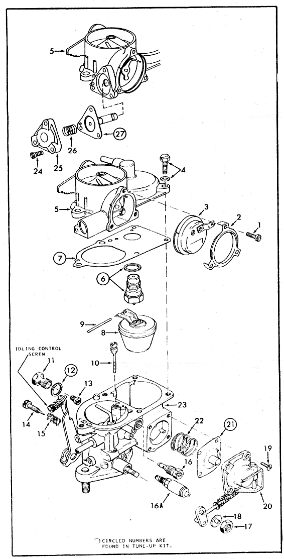
| 1 |
Retaining ring screw (3) |
15 |
Volume control screw spring |
| 2 |
Retaining ring cover |
16 |
Pilot jet |
| 3 |
Choke cover with spring and heater element |
16A |
Idling cut-off valve (30 PICT-1) |
| 4 |
Screw and lock washer, upper body (5) |
17 |
Throttle shaft lever nut |
| 5 |
Upper body assembly |
18 |
Throttle shaft lever washer |
| Needle, seat & gasket assembly |
19 |
Cover screw (4) |
|
| Carburetor body gasket |
20 |
Cover - with lever and linkage |
|
| 8 |
Float |
Pump diaphragm |
|
| 9 |
Float lever pin |
22 |
Pump diaphragm spring |
| 10 |
Air correction jet |
23 |
Carburetor main body assembly |
| 11 |
Main jet carrier |
24 |
Cover screw (3) |
| Carrier gasket |
25 |
Vacuum diaphragm cover |
|
| 13 |
Main jet |
26 |
Vacuum diaphragm spring |
| 14 |
Volume control screw |
Choke vacuum diaphragm |
Carburetor Removal
Note: 30 PICT carburetors only - Before removing the carburetor, check the operation of the idle solenoid valve. Remove the wire from it, then turn on the ignition (do not start the car). Touch the wire to the electrical connector on the idle solenoid valve. You should hear a distinct "click." If you hear the click, the valve is okay -- otherwise, it must be replaced.
-
Remove the oil bath air cleaner and set it aside.
-
Detach the fuel hose from the carburetor and quickly plug it (a pencil works great for this).
-
Detach vacuum hoses if you have them; if you have no vacuum hoses, remove the caps from the vacuum ports on the carburetor.
-
Disconnect the wire to the automatic choke heating element.
-
Disconnect the wire to the electromagnetic cutoff valve (if applicable).
-
Loosen the clamp screw in the accelerator cable pivot pin, then pull the cable out of the pin. Stow the cable pivot pin and clamp screw in a safe place so you can find them later.
-
Remove the distributor cap to provide access, then remove the two nuts (13mm) from the studs on the carburetor flange (a 13mm S-wrench is very handy for removing the pesky front carburetor nut -- available at Aircooled.Net).
-
Remove the carburetor and gasket; there will be a new gasket in your kit. Stow the two nuts in a safe place.
-
Stuff a rag into the open intake manifold to keep foreign material out.
Carburetor Disassembly
- Use the exploded view as a guide. The numerical sequence may generally be followed to disassemble the unit far enough to permit cleaning and inspection.
- Having a small container at ready, remove the main jet plug on the left side of the carburetor and drain the gasoline out of the carburetor bowl. Stow the plug where you can find it.
- Remove the five screws that hold the upper part of the carburetor to the body and remove the upper part. Remove the gasket; your carburetor kit should have a new one.
- Remove the float needle valve from the upper part; there should be a new one in your kit. This valve gets a lot of work -- you should always replace it.
- Remove the idle solenoid valve from the right side of the carburetor (if applicable).
- Remove the volume control screw from the left side of the carburetor.
- Reach through the jet plug hole (plug was removed previously) with a screwdriver and remove the main jet. The size of the jet is stamped on the top; normal size for the 30-PICTcarburetor is X125 (1.25mm diameter). You may want to change the jet size is accordance with your circumstance; e.g., smaller jet size at high altitude (X125 at 4000 ft.). Some engines (mine, for example) like to run a tad rich, in which case an X130 main jet may be appropriate.
- Remove the air correction jet (it just screws out).
- Remove the various other jets and adjustment screws from the carburetor body and store them away carefully. You will clean these and replace them. Inspect all jets, adjustment screws, and the holes they came from for wear.
- Disassemble the accelerator pump and linkage.
- Check the throttle valve shaft assembly for lateral movement (side-to-side) in the throttle shaft. If you find such movement, the shaft hole is out-of-round and you will be getting air in-leakage. This is very serious; my thinking is that if the throttle shaft hole is out of round, it is likely that the rest of the carburetor isn't in very good shape, either. When I discovered this problem I just bought a new carburetor.
- Disassemble the automatic choke assembly.
Note: You will be removing a number of small parts in this process; hopefully "stow them in a safe place" goes without saying.
Note: The manuals say that you should not remove the volume control screw, as it is set at the factory. Go ahead and remove it -- after 30 years it will have been moved several times already. "Leaving it alone" is fine for a newish engine but silly when the engines are all at least 30 years old and in different states of health. Same with the carburetors in general, so adjustments become essential. Adjustment directions are given below.
CAUTION: Brass tube type jets are not removable.
Carburetor Cleaning
- Cleaning must be done with carburetor disassembled.
- Soak parts all metal parts long enough to soften and remove all foreign material. Use a carburetor cleaning solvent and an old toothbrush on the carburetor body.
- Make certain the throttle body is free of all hard carbon deposits. Wash off in suitable solvent.
- Blow out all passages in castings with compressed air (if available -- it's best if you have it; I usually don't, but I find that "canned air" (like Ultra Jet or similar) works pretty well). Check carefully to ensure thorough cleaning of obscure areas. Do NOT use a wire or similar object to "clean" orifices!
CAUTION: Do not soak choke heating element, pump diaphragm, float, vacuum diaphragm, or any rubber parts in solvent.
Carburetor Reassembly
Reassembly of the carburetor is essentially the reverse order of disassembly, giving special attention to the special instructions below.
Replace the Following Parts -
- Accelerator pump diaphragm
- Choke vacuum diaphragm
- Float needle valve and gasket
- Carburetor body-to-cover gasket
- Main jet plug gasket
- Carburetor-to-intake manifold gasket
Special Reassembly Instructions -
- Make sure all jet orifices are clean and open. Clean with compressed air (or "canned air"). Do not use wires to check for clogged orifices.
- Check the float valve for binding and leakage. It should not be possible to blow air through the valve while the needle is pressed lightly onto its seat.
- Check the float for leaks by immersing it in hot water. If bubbles appear, replace the float.
- Check for a worn spot (depression) on the float lever where it makes contact with the fuel inlet needle valve. Replace float assembly, if necessary. Float assembly may be purchased at local VW dealer, P/N 113-129-391 rectangular shaped float (22).
- The proper needle seat gasket must be used for the specific type of carburetor. Both the 28 PICT and 30 PICT carburetors use the 1.0mm (.040") gasket.
- When installing the pump diaphragm and spring, make sure the larger end of spring is properly seated in the carburetor body cavity. Be sure to install the diaphragm with plunger toward pump cover. See the exploded view above.
- Be sure to use the correct body joint gasket; there will probably be several in your kit. Use the old one for comparison.
- Check the thermostatic spring in the automatic choke housing for damage. If it is distorted or "kinked", replace the assembly.
- Make sure the electrical heating element is not broken. This can be checked with an ohmmeter or connected to a correct voltage battery for a few minutes to see if it warms up. (Be sure to ground the inside metal part of the housing in order to complete the circuit.)
- When installing the choke assembly with spring and heater element, carefully rotate the assembly counterclockwise, making sure that the hook on coil end engages with the lever on choke shaft. Continue rotating approximately 1/8 turn more until index marks align. Then tighten screws securely. (See our Automatic Choke Adjustment Procedure.)
Note: It is very important that you install the correct needle seat gasket. This gasket sets the fuel height in the float bowl; erratic behavior may result if the gasket is not correct.
Carburetor Installation
- Install in reverse order of removal.
- Lightly lubricate the choke valve shaft and throttle valve shaft with engine oil and the external linkage with molybdenum grease.
- Using a new gasket, install the carburetor on the intake manifold; torque the retaining nuts to 14 ft-lb (just snug them up tight with your 13mm box-end wrench). Again, a 13mm S-wrench is very handy for snugging up the front carburetor nut -- available at Aircooled.Net. Be careful that you don't tighten these nuts too much -- you may strip the stud out of the base of the carburetor.
- Secure the fuel hose with a new hose clamp.
- Pass the end of the accelerator cable through the cable pivot pin installed in the throttle lever. Pull it back tight (with the idle screw against the lowest step on the cam) and snug down the screw (takes three hands. I use my channel lock pliers and hold the end of the cable to the throttle lever while I tighten the screw with the other hand). See our Accelerator Cable Adjustment Procedure.
Idle Adjustment -
- Warm up the engine. Check to make sure the automatic choke is fully open.
- Set the idling speed to 850 rpm with the idling control screw on the top of the throttle lever (see exploded view above).
- Turn the volume control screw (Item #14 to the right until the engine speed starts to drop.
- From this position, turn the volume control screw to the left until the engine runs fastest.
|