Intake Manifold

~ Removal/Installation Procedure and Discussion. ~

(For dual-port engines)

See also our discussion of the Heat Riser Flange connections to the muffler, and cracking of the intake manifold that can result from too much stress.

~~~

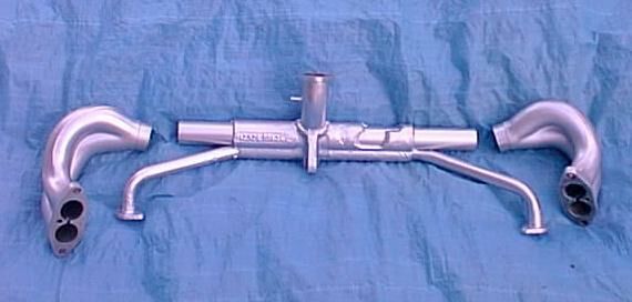
Dual-Port Intake Manifold (Disassembled)

~~~

Intake Manifold Removal Procedure -

With the engine in the car, you must partially remove the fan housing before you can completely remove the intake manifold, or before you can remove the alternator. However, it you are only removing the manifold end pieces, you do not need to remove or partially remove the fan housing. Steps in this procedure shown in red do not need to be performed if you are only removing the end pieces.

  1. Remove the drive belt as follows -

    1. The front half of the alternator pulley has two cut-out slots in it. Inserting a thin screw driver in either slot locks the pulley so you can loosen/tighten the 19mm retaining nut. Remove the retaining nut on the alternator shaft with the 19mm wrench, then slip off the washer, any spare shims, and the outer pulley half. Take note of how many shims are between the pulley halves so you can easily re-tension the fan belt on reassembly.
    2. Slip the belt off the crankshaft pulley and remove it.
    3. Remove the inner pulley half, being careful to remove the Woodruff key and stow it and the shims and nut in a baggie in a safe place.

  2. Remove the air cleaner.
  3. Detach the accelerator cable from the throttle lever and remove the fuel line from the fuel pump to the carburetor.
  4. Remove the carburetor.
  5. Disconnect the incoming fuel line to the fuel pump and plug it.
  6. Remove the fuel pump, as it will be in the way later when you need to secure the manifold tongue to the engine case.
  7. Pull out the accelerator cable guide tube and pull the accelerator cable forward, out of the fan housing.
  8. Remove the cable from the negative terminal of the battery.
  9. Label and then detach the electrical connectors from the alternator.
  10. Disconnect the wire to the backup lights at the in-line fuse (where fitted).
  11. Remove the strap that holds the alternator to the support.
  12. Disconnect the ignition cable from the coil and the fresh air tubes on either side of the fan housing. Disconnect the spark plug wires from the attachments in the fan housing (three places).
  13. Remove the engine lid and the engine lid hinge brackets. You must remove the brackets to get enough clearance to lift the fan shroud.
  14. On the left side of the car, reach down in front (front) of the fan housing with a 10mm box-end wrench (ring spanner) and remove the bolt for the oil cooler cover and the bolt that holds the fan housing to the oil cooler flange. This is awkward and you'll be working largely by feel.
  15. Note: If these two connectors are cheese-head screws, replace them with 10-mm hex-head bolts. This will save you lots of trouble installing them and removing them next time (10-mm open-end wrench (ring spanner) instead of an offset screwdriver.

  16. Remove the oil cooler cover and the air duct.
  17. Unbolt the thermostat and unscrew the thermostat from its rod.
  18. Disconnect and remove the connecting link between the cooling flaps in front of the fan housing (don't lose the spring).
  19. the two bolts on either side of the fan housing. The one on the left also supports the metal fuel line, and you may need to disconnect this line from the fuel pump to move it out of the way.
  20. Raise the fan housing enough so you can remove the four mounting bolts from the outer fan cover on the rear of the shroud. This will allow the alternator/fan assembly to be removed.
  21. Note: The fan housing can be removed completely at this point if desired. If the fan housing is simply raised, it helps to support it on either side with wooden blocks. (It's really easier to just pull the fan housing out of the car.)

  22. Loosen the clamps on the two boots that connect the intake manifold pieces together (two on each boot).
  23. Remove the shrouds from around the preheater tubes (if they are there).
  24. Remove the nuts and bolts that attach the preheater tubes to the exhaust header. (You don't need to do this if you are not removing the center section of the intake manifold.)
  25. Remove the nuts (two on each side) that attach the intake manifold end pieces to the cylinder heads.
  26. Slip loosen the hose clamps on the polyethylene boots that connect the intake manifold end pieces to the intake manifold center section, and lift off the end pieces.
  27. Lift the fan shroud enough to slip the manifold under it (if you have not previously removed the fan shroud).
  28. Remove the nut that secures the center section of the intake manifold to the engine block, and lift the intake manifold center section off of the engine.

~~~

Intake Manifold Installation Procedure -

  1. Clean and inspect the manifold, paying particular attention to the flanges and preheater tubes. Remove any carbon buildup from the passages.
  2. Inspect the flanges on the intake manifold ends to make sure there is no foreign material on them and that they are not warped. This can be a significant source of air inleakage. Sand the flanges on a flat surface if necessary.
  3. Make sure there is a stud protruding from the engine case to which the manifold tongue can attach. It is very important that the intake manifold be snugged up tightly against the engine case at this point.
  4. With the fan housing raised or removed, slip the center section of the intake manifold under it and into place.
  5. Note: Since the manifold center piece has to slip under the alternator stand, it is easiest to assemble the manifold piece-by-piece.

  6. Smear a thin layer of Permatex Ultimate Grey sealant (or similar) on both sides of a metal dual-port intake gasket, and place the gasket over the studs in the cylinder head on the right-hand side.
  7. Smear a thin coating of wheel bearing grease inside the lips of the polyurethane boots.
  8. Note: The grease is not meant to be a sealant, but a bit of grease makes the boots stay supple and allows them to be fully tightened up by the hose clamps.

  9. Slip a new polyurethane boot and two clamps (note the size difference onto the right-hand side of the manifold center piece.
  10. Place the right-hand end casting down on the cylinder head studs (no nuts or washers yet). At the same time, slip the right-hand end piece into the polyurethane boot on the center piece, but don't tighten the hose clamps yet.
  11. Note: This may be a tight fit. You may need to carefully tap the end pieces in place with a hammer and drift.

  12. Fit the left-hand end piece the same way.
  13. Tightened all four of the end-piece/cylinder head nuts evenly and securely (tight but not TOO tight - the studs in the cylinder head aren't very big).
  14. Install the pre-heat tubes into the intake manifold center piece, and attach the flange on the other end to the exhaust header with bolts, washers and nuts. Tighten securely.

    Note: In the aftermarket intake manifolds that are available today, the pre-heat tubes come as separate pieces. It may be necessary to bend the tube a bit to make them fit, both into the holes in the center section of the intake manifold and where they attach to the exhaust header. If you find it necessary to bend them, do so carefully so the tubes doesn't become kinked.

  15. Tighten the four hose clamps on the two polyurethane boots that connect the intake manifold pieces together.
  16. Make sure the top of the manifold is level (assuming the surface you are working on is level), then bolt the manifold tongue on the bottom of the center section of the manifold to the stud that protrudes horizontally from the engine case, using a large washer and 13mm nut. Make sure the manifold tongue is resting tightly against the engine case.
  17. Note: If you may find (as I did) that the stud in the engine case to which the manifold tongue is too attach appears to be too short to get a nut on it. This is probably because you do not have the manifold tongue snugged up tightly against the engine case. And this may be because the pre-heat tubes are installed incorrectly in the center section of the intake manifold.

  18. Lower the fan housing partially into place, keeping it raised enough to replace the alternator/fan assembly and the four mounting bolts that hold it in place (if you removed the alternator/fan assembly).
  19. Lower the fan housing the rest of the way and attach the two bolts on either side.
  20. Note: If these two connectors are cheese-head screws, replace them with 10mm hex-head bolts. This will save you lots of trouble reinstalling them and removing them next time (10mm open-end wrench instead of an offset screwdriver).

    Note: may need a flat-head screwdriver to pry open the cylinder tin slightly to accommodate the shroud. (The shroud tin goes INSIDE of the cylinder tin, all the way around.)

  21. Install and connect the connecting link between the cooling flaps in front of the fan housing. Be sure to properly install the spring.
  22. Screw the thermostat back onto the connecting rod and adjust and tighten the thermostat in place. See our Thermostat Installation procedure.
  23. Replace the oil cooler hot air exhaust and the oil cooler cover with 10mm hex-head bolts.
  24. Replace the engine lid hinge brackets and the engine lid.
  25. Reconnect the fresh air tubes on either side of the fan housing and the ignition cable into the coil.
  26. Reattach the spark plug wires to the spark plugs (if you removed them) and the wires into the attachments in the fan housing (three places).
  27. Replace the strap that holds the alternator to the alternator stand.
  28. Reconnect the wire to the backup lights, reinstalling the in-line fuse in the process.
  29. Reattach the electrical connectors to the alternator.
  30. Reattach the cable to the negative terminal on the battery.
  31. Replace the accelerator cable guide tube that runs through the fan housing and run the accelerator cable back through it into the engine compartment.
  32. Replace the carburetor and reinstall the idle cutoff valve.
  33. Replace the distributor (if removed) and the distributor cap.
  34. Replace the wire to the automatic choke.
  35. Replace the fuel line to the fuel pump and from the fuel pump to the carburetor and snug down the hose clamps on either end.
  36. Re-attach the accelerator cable to the throttle lever by way of the barrel clamp at the base of the throttle lever.
  37. Replace the air cleaner.
  38. Replace and adjust the drive belt. See our Drive Belt Replacement/Adjustment procedure.

Sit down and enjoy a cold one. You deserve it! Then take your baby out for a spin and notice that she doesn't stumble on acceleration any more!

~~~

Some Questions and Answers

A question came up regarding the reasoning behind the three-piece manifold. It seems like this just gives the VeeDubber one more thing to watch for, the guy wrote, to make sure air isn't getting sucked into the manifold around those rubber expansion joints.

Rob responded - The ‘71 model got the 34PICT/3 carburetor and three-piece manifold. My theory is this -- (regarding the one-piece/three-piece switch)-- the cylinders actually 'walk' front/ back, and up/down a few thousandths when the engine is running (the heads are clearanced to allow for this). Also the iron cylinders and aluminum heads expand at different rates with. This makes the engine change shape fractionally with heat. The one-piece manifold, with it's soft copper gasket at the heads, is probably at the limits of it's capacity to stretch with this engine movement on the 1500cc engine (it runs colder than the engine remember, so doesn't expand as much), and with the greater heat of the 1600cc engine, they needed to alter the design.

I also wonder if the VW engineers weren't anticipating an extended stroke for another increase to say 1700cc. An extended stroke would have required a wider engine, and the three piece manifold could cope with this okay.

A question regarding the differences in head design - On p. 1-17 of the Bentley manual there is an exploded view of the cylinder head. Two heads are shown: the 1970 head, and the 1971 and later head. The major difference appears to be that the 1971 head is dual port, whereas previously the head was single port. Is this correct? And as I look at the 1971 head it shows two studs that the intake manifold attaches to. It is at this point that there is a compressible copper gasket, right? If the nuts are not sufficiently tight this would be a very likely place for air inleakage. I don't find a torque specification for these nuts in the Technical Data section; do you know what torque they should be tightened to?

Rob responded - In 1970 the U.S. got the first 1600cc engine, but that was with the single port heads, same as my 1500cc engine. I think the valve sizes may be a bit larger on the twin port heads too. The gaskets on the dual port are paper. The Mid-America Motorworks catalogue has a photo of a twin carburetor setup with the gaskets on the right hand side (black -- 'double ring' shape). I don't remember the torque setting -- but it wasn't very much (small studs).

The '71 manifold was also designed for the 34 PICT carburetor. The 34PICT came with the first 1600cc dual-port engine in the ‘71 model year. ’71-‘73 had the dual vacuum distributor (DVDA) with the 34, then '74+ got the single-vacuum dual-advance (SVDA) distributor and still kept the 34 PICT carburetor.

A question - I've been having a frustrating time myself getting the old manifold out and putting the "new" one back in. Can you give any advice?

Dave responded - On my '73 SB I have to strip pretty much everything off of the engine (carburetor, alternator, etc.) to get the intake manifold out. And to do that, of course, it's just easiest to remove the fan housing.

Rob responded - I found that by removing the left dual port "corner" manifold piece and lifting the fan assembly with generator attached I could finangle the new manifold centre section in. Since my Bug doesn't yet have cooling flaps back in (hard to find here -- sadly almost all VW's have had them removed and junked!) I could lift the fan without worrying about the thermostat linkage.

Rob reports experience with an engine running on only two cylinders - The two right cylinders are running, so you know you're getting petrol into the system. And you know that the two plugs on the left are firing, which means that somehow between the carburetor and the cylinders the fuel mixture on that side is outside the 1.4% - 7.6% flammable range for petrol. There's no way it could be high, so excess air in the system on that side is the only logical conclusion.

I even tried pulling back the rubber boot on the left side of the manifold to see if I could spray WD40 in there for a test, but the right cylinders wouldn't fire with the left boot off. It was this which finally made me think it MUST be the left dual port manifold-to-head piece, since that was the furthest away from the right cylinders which were obviously getting a "close enough" mixture to run.

Finally I just sat and looked, then tried moving the left rubber boot to try the WD40 trick at the left cylinders, which settled the thought about where the leak had to be, even though I couldn't see it and WD40 near the head/manifold joint didn't make any effect (couldn't get the straw right down there, and the leak must have been over too wide an area).

(Later) It turned out to be the removed dual port manifold piece which had not snugged down properly. When it's in the car, the bolts for that piece are almost impossible to reach -- socket with 1-foot extension bar for the front nut and an open-end spanner for the rear bolt, turning it 1/12th turn at a time and flipping the spanner over each 1/12th (the heads are angled 1/6th turn). So it had not bedded down and I couldn't see that from above it. After loosening and a good wiggle I got an extra 2-3 turns on the nuts and it's fine now. Idles smooth, lots of power.


* * * * *


Design by Erin