|
||

|
|
Engine TinThe engine compartment designe in a VW, including the tinware surrounding the engine, is an important feature of the VW beetle. The tinware around the engine is designed to seal the upper side of the engine from the underside. Fresh cooling air enters the upper engine bay through the under-window slots (and the engine lid slots where fitted), goes through the fan and is blown down over the cylinders and heads, and out under the rear of car. The tinware around the engine is designed to keep these air paths separate so you never get used hot cooling air sucked into the cooling fan. Air-cooled VW engines run quite close to their heat limits to begin with, so the margin of safety is small. Make sure that ALL of the tinware is in place, properly fit, well secured and in good condition.
 Volkswagen Engine TinThe Volkswagen cooling system is neat and simple. A multi-bladed centrifugal fan is mounted on a shaft which is simply an extension of the generator armature shaft. The cooling fan is designed to suck air into the fan housing. It rotates in a sheet steel, semi-circular housing called the fan shorud, drawing in air through the fan centre and directing it down to each pair of finned cylinders. Cooling air then directed by the cooling flaps and tinware over the cylinder heads and cylinders.
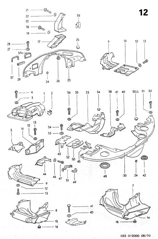
 Cooling TinwareThe cooling tinware in the sketch above is shown in red. The cylinder heads and cylinders are shrouded by carefully designed sheet steel covers (the engine "tin" or "tinware"). The tinware directs the cooling air from the fan housing. Below each pair of cylinders a contoured deflection plate is mounted centrally. Thus the air is directed over the full surface area of the cylinder cooling fins. In order to shorten the warming up time a thermostat is mounted below the right hand pair of cylinders. This is a conventional bellows type and it operates a restriction on the through flow of air when the engine is cold. The thermostat opens flaps in the fan housing when the engine warms up, so allowing the full airflow to pass round the cylinders. Also in this fan housing, bolted to the top of the crankcase, is an oil cooler that stands up in the stream of air like a radiator and cools the oil, which is pumped through it. This makes the engine both directly air cooled, and also oil cooled, and a LOT of heat is removed via the oil cooler. There are two different oil cooler designs. The arly version (pre 1971) has the oil cooler stnading up in the cooling airstream for the left cylinders, so they tend to run a little hotter than the right side cylinders. That worked Ok until the engine horsepower increased towards 60hp, then they started having problems with occasional broken exhaust valves, particularly No3 (left front) cylinder. In 1971 they introduced the "doghouse" cooling system, which moved the oil cooler out of the main cooling airstream and into it's own "doghouse" with a separate supply of cooling air from the now larger cooling fan. All cylinders then got nice cool cooling air, and more of it too. Apart from the large piece of cooling tinware around the rear of the engine (the rear breastplate), the remainder of the cooling components and cover plates fitted to the engine cannot be removed unless the engine is removed from the vehicle. There is a tendency for the "cheesehead" screws holding the tin work to disappear over time, but these are commonly available from almost any air-cooled VW parts outlet for a few cents each. Replace them when you find them missing.
Note: Before installing the fan shroud, the doghouse oil cooler tin, and the firewall tin (front-most), you must install at least the cylinder cover plates. However, you want to install the oil cooler before installing the left cylinder cover plate; other wise access to the oil cooler adapter nuts is very difficult. The engine tin is installed at the longblock buildup proceeds not all at once. Make sure all of the fastening bolts are in place and snugged down tight. Heres the approximate sequence
Notes -
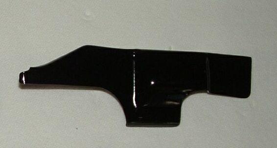
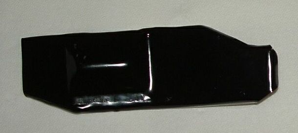
Left and Right Rear Deflector TinsNote: The two cover plates are a right and a left, so make sure that you get the correct orientations. You may have to do some minor modification so that the manifolds will clear the lip of the tin. Again Install the oil cooler adapter before installing the left cylinder cover plate. Rob wrote in response to a query about the piece of tin that wraps around the lower part of the engine pulley (Part #38 - see the engine tin diagram above). I bought my 1970 Beetle brand new, and it has the #38 piece on it -- it's just a cover which stops you dropping screwdrivers, etc. down under the engine pulley, as it fits very closely around the pulley and belt, exposing only the top of the engine pulley. Absolutely no effect on the cooling if it's not there. I haven't seen it on later engines. One piece I do see missing on many engines is Part #11 (deflector tin) and it's counterpart on the right side (not shown in the diagram). These fit on the rear side of the cylinder tins and force the cooling air down past the cylinder fins, and encourage airflow past the very hot exhaust ports in the heads, before allowing the air to turn rearwards through the air exit. They might not seem like much, but they are a very important part of the cooling system -- almost as important as the under-cylinder deflectors (Part #5). The deflector tins are easily installed with the rear engine breast plate (Part #30) removed - one of the bolts (on each side) that secures the breast plate also secures the deflector tin. Another piece often missing is the small deflector plate under, and in the center of the heads - it works like Part #5 to force air fore and aft through the finning. Without it the heads run very hot underneath, and without Part #5 the cylinders run hot underneath.
|
||||
|
|