|
||

|
|
Accelerator Pump DiscussionThe following subtopics are discussed in this article -
General Discussion(34 PICT/3 Carburetor)To get an engine to accelerate smoothly, you need both an advance in the timing and an increase in fuel flow. The vacuum distributor senses when you open the throttle and provides the extra advance timing. It is the duty of the accelerator pump to provide the increase in fuel flow. When you open the throttle, the airflow increases immediately but the fuel (being more dense than air) takes a moment to catch up with the increased airflow. This would result in a lean mixture for a few moments (the car would hesitate), so the carburetor has an accelerator pump built into the side of it which supplies a shot of fuel to ensure smooth acceleration. The accelerator pump connected by a linkage to the accelerator; when acceleration is required, the pump squirts a spray of fuel directly into the throat of the carburetor to momentarily increase the fuel-to-air concentration. You can see it operate if you pull the air cleaner off and look down the carburetor throat. There is a small bent brass pipe right pointing right straight down the throat of the carburetor-- this it the delivery tube. Grab the throttle arm and pull it firmly (like you were pushing down on the accelerator). You should see a squirt of fuel from the delivery tube straight down the throat of the carburetor. If you pull on the throttle arm very slowly you'll see that the accelerator pump does nothing -- no squirt. It's set that way because when you open the throttle slowly the fuel flow has time to keep up with the increasing airflow - no extra shot of fuel is necessary. We want as little accelerator pump squirt as possible to remove the stumble from the engine. Too much gas will wash the oil off of the cylinder walls (wearing out the pistons and rings) and will reduce the miles per gallon. so be conservative in your adjustment of the accelerator pump.
Measure the "Squirt"(34 PICT/3 Carburetor)The 34 PICT/3 carburetor has a bell-crank with an adjusting bolt on the right side of the carburetor (see the Exploded Figure in our Carburetor Disassembly and Cleaning procedure, as well as the picture below). The quantity of gasoline that is injected upon acceleration can be measured, as follows -
Note: Maybe you can get the tubing on the end of the injector without removing the top off of the carburetor -- I sure couldn't! Save yourself some grief -- it's only five little bolts.
Rob suggests another method that might be easier - To measure the accelerator pump squirt, it's easiest to just take the carburetor completely off, being careful to no spill fuel out of the carburetor bowl. Put a container (e.g., a glass jar etc.) under the carburetor throat, then pull the throttle arm smartly - you should get 1.4-1.6cc (ml). If you operate the arm say five times you can then measure the 7-8ml easy enough. Divide the volume you obtain by the number of times you operated the throttle arm. Don't operate the arm much more than five times, as the fuel level in the bowl will be diminishing each time you pull the throttle arm - eventually you'll run out of fuel in the float bowl. Adjust the Injection Quantity(34 PICT/3 Carburetor)
 Please note carefully: It is the ADJUSTING SEGMENT that you turn counterclockwise to increase the injection quantity, NOT the retaining bolt. If you do it backwards, you'll have a terrible "stumbling on acceleration" problem. (Once again, "Voice of Experience!")
Pump Linkage/Alternator Interference
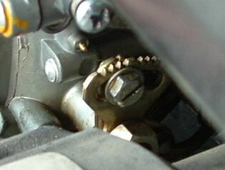
On our 1971 1600dp engine, equipped with a 34PICT/3 carburetor and an alternator (1971 engines had generators), we found that the accelerator pump linkage was impinging on the alternator in two places -- the accelerator pump adjustment screw, and immediately forward of the accelerator pump itself. We couldn't see the latter interference readily because of the air cleaner and the automatic choke. This interference was preventing the idle screw from touching the choke cam like it's supposed to, thus making it impossible to properly tune the carburetor. This interference was puzzling to us at first -- the intake manifold and heat riser assembly is all in one piece, and we thought surely that the alternator was designed to fit. This was before we realized that this assemblage of components was designed to work with a generator, not an alternator. The alternator is larger in diameter than the generator, especially at the rearward end. Rob suggested that we raise the carburetor so that the accelerator pump linkage would clear the alternator. He wrote - It would be a very simple job for a workshop to make a spacer out of brass for you (to fit under the carburetor to raise it up). You'd just need to take one of the gaskets to them to use as a pattern, and decide how high it needs to be (1/2 inch or so?) Then use a gasket on both sides of the new spacer and you are in business. 2-3 gaskets under the carburetor might be enough, if you can't get a spacer. I'm not sure about the bolt length on the carburetor though -- you might have to replace the studs with longer ones or use through-bolts. If they currently have a little spare thread under the nut, measure this length and determine whether this thickness spacer would give you enough lift. Even 1/4-inch might do it. We finally solved the interference problem three ways -- we raised the carburetor a bit with three home-made gaskets, ground a bit off of the adjusting bell and nut, and ground just a titch off of the alternator body with a Dremel.
|
||
|